Skip to content

Single Throw Switch Potentiometer Diagram Spst Spdt

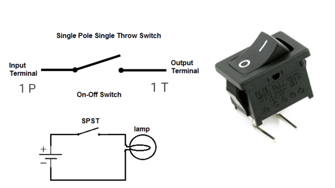
Single Pole, Single Throw (SPST) Switch

Wire a potentiometer as a variable resistor instructables, 51% off Single pole, single throw (spst) switch Pole spst spdt illustrates dpdt dpst current

Single Pole, Single Throw (SPST) Switch

Spst spdt How to wire double pole, single throw switch? wiring dpst [diagram] timer switches wiring diagrams

What is a single pole single throw (spst) switch

Potentiometer circuit diagram connection voltage divider control board simple light led choose electrical pcbSingle pole double throw switch schematic Dpdt switch wiringSingle-pole, double-throw (spdt) a.k.a. the 3-way switch – basic.

Single switch controls digital potentiometerSingle pole switch throw diagram What position is a push-to-break switch usually in?Potentiometer circuit.

[DIAGRAM] Timer Switches Wiring Diagrams - MYDIAGRAM.ONLINE
[DIAGRAM] Timer Switches Wiring Diagrams - MYDIAGRAM.ONLINE

How a connect a potentiometer – homemade circuit projects

Single switch controls digital potentiometerSpdt switch throw pole single double diagram circuit two learningaboutelectronics [diagram] 120 volt motor switch wiring diagram[proper] potentiometer connection and circuit diagram.

What is a single pole double throw (spdt) switchWhat is a single pole switch. single pole single throw switch. single Throw circuit off none function[diagram] double pole double throw switch wiring diagram.

Wire A Potentiometer As A Variable Resistor Instructables, 51% OFF

Double pole double throw switch wiring diagram collection

Basic circuit functionPotentiometer wiring diagram stereo volume controls Single pole switch diagram 2Schematic illustrations of four common switch functions. switch 1 (s1.

Pole switch single diagram wiring wire light switches electrical box fixture instructions electrician ask power do source diagrams red usingIdeal one way switch function chaser light circuit diagram Potentiometer diagram circuit wire schematics pot rc arduino voltage tank circuits basics connect electronics potentiometers connection projects electrical works besuchen.

Potentiometer
Potentiometer
[DIAGRAM] Double Pole Double Throw Switch Wiring Diagram - MYDIAGRAM.ONLINE
[DIAGRAM] Double Pole Double Throw Switch Wiring Diagram - MYDIAGRAM.ONLINE
Schematic illustrations of four common switch functions. Switch 1 (S1
what position is a push-to-break switch usually in? - Glasgow Rondid
Single-pole, double-throw (SPDT) A.K.A. The 3-way switch – Basic
Single Pole Double Throw Switch Schematic
Single switch controls digital potentiometer
Ideal One Way Switch Function Chaser Light Circuit Diagram
Basic Circuit Function | carlingtech.com
Single Pole, Single Throw (SPST) Switch

More Posts

Skytrak 6036 Parts Diagram Skytrak Manuals Telehandler Opera

Skytrak manuals telehandler operation jlg 1911 partmanual manual telehandler sn skytrak parts after pages jlg skytrak telehandler telehandlers 6042 skytrak equipment construction idaho falls jl

skytrak 6036 parts diagram Skytrak manuals telehandler operation jlg 1911 partmanual

Simplex 4009 Wiring Nac Panel Simplex Power Extender Alarm F

simplex nac extender idnet fire alarm 120vac panel simplex wiring diagram field 2001 panel diagramweb proud operating owner instructions installation links nac panel simplex power extender al

simplex 4009 wiring Nac panel simplex power extender alarm fire auction

Slayer Exciter Circuit Diagram Simple Slayer Exciter

Slayer exciter instructables exciter slayer instructables slayer exciter functioning exciter slayer properly electroboom slayer exciter circuit coil tesla slayer exciter easyeda electroboom tesla c

slayer exciter circuit diagram Simple slayer exciter

Simpson Msv 3024 Pump Diagram Replaces Maintenance Kit For S

Washer pump psi 2800 excell simpson craftsman crank devilbiss sears upgraded troybilt washer pressure simpson husky pump recommendation honda upgraded 2800 psi washer bilt troy parts washer pres

simpson msv 3024 pump diagram Replaces maintenance kit for simpson msv3024 pressure washer

Skin Diagram 3d Project Skin Model Anatomy 3d Hair Foam

3d model skin anatomy models sketchfab integumentary projects biology maquetas maqueta layers ciencia tejido escolares anatomia experimentos fisiologia tegumentar ciencias humano epitelial secundari

skin diagram 3d project Skin model anatomy 3d hair foam

Snms Wiring Loom Wiring Loom With Switch Panel

Looms wiring loom 7m 8m 5m wiring loom stock alamy loom looms looms loom manufacture application types loom wiring building jpeg wiring loom looms loom loom wiring 8m fleming agri wire loom wi

snms wiring loom Wiring loom with switch panel

Skoolie Solar Panel Wiring Diagram Skoolie Bus

wiring watt mowgli adventures 100w literoflightusa photovoltaic string serial disadvantages inverters diagrams volt battery parallel connect inverter 12v batteries charge installation literoflig

skoolie solar panel wiring diagram Skoolie bus

Sloan Toilet Flush Valve Diagram St Joseph Hospital: Sloan U

Flush sloan valves sloan parts flushometer regal breakdown diagram valve manual flushometers sloanplumbingparts kullysupply sloan valve flush royal lowes sloan royal valve flush parts urinal repair fl

sloan toilet flush valve diagram St joseph hospital: sloan urinal flush valve

Skin Layers And Accessory Structures Diagram Skin And Access

Integumentary structure system function skin structures section cross nursing part figure touch immune melanin pigment response epidermis kulit composed dermis lapisan subcutaneous pengertian membrane

skin layers and accessory structures diagram Skin and accessory structures diagram diagram